Aluminum plate&bar coolers feature a wide variety of thermally efficient internal and external fin patterns. Fins are laid between aluminum braze sheets and fitted with header and face bars. The assembled unit is placed into one of our modern brazing furnaces where precise control of time and temperature produces a unified core. Manifolds designed to meet each customer's particular piping requirements are welded into place to complete the cooler. We can also supply cores when manifolds already exist or must be fitted in the field.
These strong, compact, light-weight coolers are ideal for both on- and off- highway markets. We can also supply the complete cooling package consisting of a combination of coolers, fan guard and motor.
From small individual coolers to large complex engine cooling systems, Better-Tech can design and manufacture the heat transfer solution that's right for you. Our engineering team is continually developing additional fin geometries to improve heat transfer efficiency so we can meet or exceed your expectations.
Engine cooling systems
· Charge air coolers
· Radiators
· Oil coolers
· Aftercoolers
· Combination coolers
Aluminum Plate Bar Coolers Producing Process:
Blanking -> Fin Punching - > Cleaning - > Core Assembly- >Vacuum Brazing ->Part Machining
-> Welding-> Pressure Test -> Drying ->Overall Inspection- Painting -> Packaging
Aluminum Plate Bar Coolers Structure:
Aluminium Plate Bar Coolers Application:
Plate Heat Exchanger,Bar Heat Exchanger,Plate Fin Heat Exchangers, Brazed Aluminum Heat Exchangers,Finned Heat Exchangers Wuxi Better Technology Co., Ltd , https://www.btheatexchanger.com
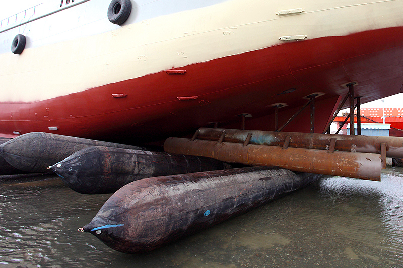
Ship launching airbags are to be constructed of a cylindrical body and two conical heads (one at each end). Ship launching airbags with lots of advantages, such as easy to operate, time saving, saving investment safety, etc.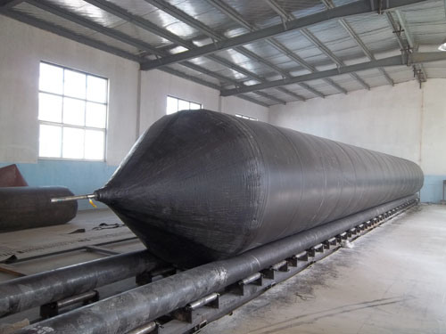
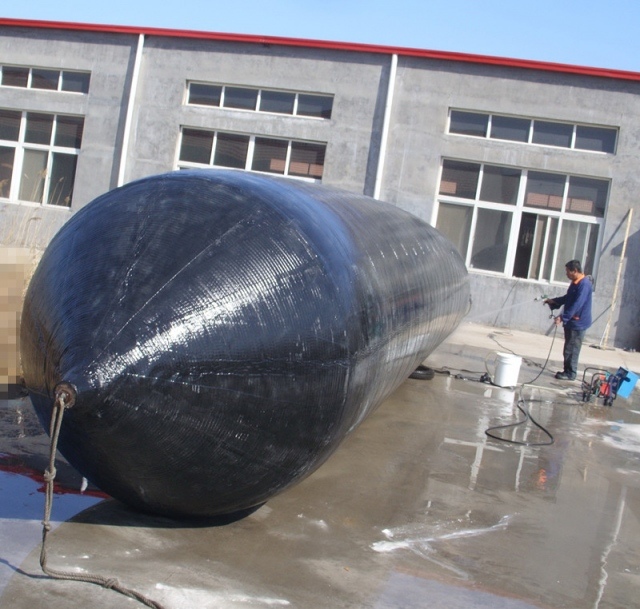
Major Strengths of Ship Launching Airbags:
High level of safety: Equipped with a reliable safety valve, our airbags can stand the maximum pressure up to 4 times that of the operating pressure.
Good air tightness: Pressure decreases less than 10% for a period of 24 hours.
Long lifespan: It is guaranteed that our airbags can sustain their designed operating pressure for 3 years.
Specification
1. Structure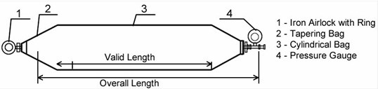
2. Diameters: 0.8 m - 2.0 m or customized.
3. Length: 6 m - 20 m or customized.
4. Loading Capacity: about 10 T/M to 40 T/M.
5. Grades:
Ordinary airbags - 3, 4 or 5 layers of synthetic-tire-cord.
High bearing capacity airbags - 6, 7 or 8 synthetic-tire-cord.
Super high bearing capacity airbags - 9, 10 or more layers of synthetic-tire-cord.
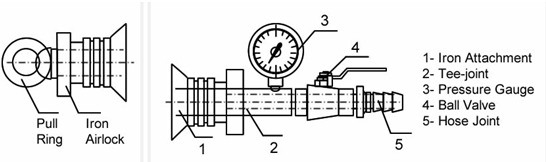
6. Accessories: Pull ring, iron airlock, tee joint, pressure gauge, ball valve, hose joint etc.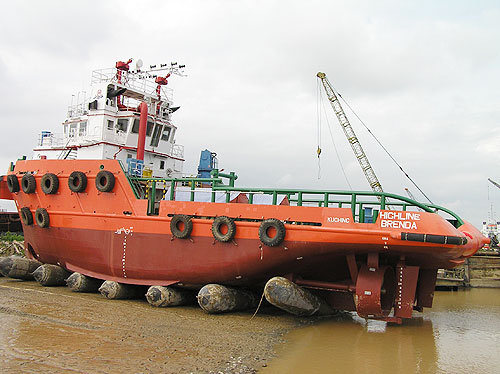
7. Technical Data of Ship Launching Airbags
Model
Diameter
(m)Initial pressure
(KPa)Rated working pressure,
Pe (KPa)Bearing capacity (kN/m)
Minimum burst pressure (KPa)
QP3
0.8
25
130
114
390
1.0
18
100
110
300
1.2
15
85
112
260
1.5
13
70
115
210
QP4
0.8
35
170
149
510
1.0
25
130
143
390
1.2
20
110
145
330
1.5
16
90
148
270
1.8
14
80
158
240
QP5
0.8
48
210
184
630
1.0
35
170
186
510
1.2
28
140
185
420
1.5
20
110
181
330
1.8
16
90
178
270
QP6
1.0
45
200
219
600
1.2
32
165
217
490
1.5
25
130
215
390
1.8
20
110
218
330
Note:
1. Rated working pressure:±5%.
2. Compress deformation: ±2%.
3. Bearing capacity: one meter airbag at a deformation rate of 70%, internal pressure equivalent to the rated pressure value of Pe.
9. Rubber Material Test:
No.
Test item
Required value
Test method
1
Tensile Strength, MPa
≥ 18
ISO37
2
Elongation at break, %
≥ 400
ISO37
3
Hardness, shore A
60±10
ISO7619-1
4
Tear Strength N/cm
≥ 400
ISO34-1
5
Compression set, % (70 ºC ± 1 ºC, 22 h)
≤ 30
ISO815-1
6
After thermal aging at
(70 ºC, ±1 ºC, 96 h)Holding of pull lengthening,%
≥ 80
ISO188
7
Holding of elongation at break,%
≥ 80
ISO188
8
Change of hardness, hardness
≤ 8
ISO7619-1
9
Static ozone aging at 40 ºC*96 h,
{ozone concentration( 50±5)*10}No crack
ISO1431-1
10. Reinforcing Material: the warp should be (90±5) cord per 100 mm in width, and the breaking strength shall be more than 205 N per cord.
Â
11. Appearance: The appearance of an air bag shall be smooth, glossy and without blemish such as crack, blister, delamination pits or impurities.
Â
12. Dimensional Tolerances:
The length and diameter of an airbag shall be measured with the rated working pressure and be within ±3%.
Â
13. Ship Launching Airbags Performance:
D
(M)(4-5 layers)
(6-8 layers)
Â
Initial pressure
(MPa)Working pressure
(MPa)Initial pressure
(MPa)Working pressure
(MPa)Â
Â
1.0
0.14 - 0.16
0.12 - 0.14
0.22 - 0.26
0.20 - 0.24
Â
1.2
0.12 - 0.14
0.10 - 0.12
0.20 - 0.24
0.17 - 0.22
Â
1.5
0.10 - 0.12
0.08 - 0.10
0.15 - 0.20
0.13 - 0.18
Â
1.8
0.08 - 0.10
0.07 - 0.09
0.13 - 0.16
0.11 - 0.14
Â
2.0
0.07 - 0.09
0.06 - 0.08
0.12 - 0.15
0.10 - 0.13
Â
Â


CCS Marine Rubber Ship Launching Airbag for Vessel Launching
Diameter: 0.8m-2.0m
Length: 5.0m-18m
Layers: 4-10
Characteristic: Anti-Explosion, Flexible, High Bearing Capacity,
Warranty: 24 Months
Working Age: More Than 10 Years
Trademark: DACHENG
Transport Package: Natural Rubber & Synthetic Cord Layer
Specification: as drawings
Origin: China
HS Code: 4016950090
Introduction