April 19, 2025

Straight face crankshaft manufacturing technology and special process

The advanced crankshaft processing lines are generally relatively short, but they have high efficiency and large output. The crankshafts processed are of good quality and stable. For example, the Ford engine plant crankshaft production line in the United States has only 17 processes, covers an area of ​​6967m2, but the annual output of V8 engine ductile iron crankshaft is 535,000. Its advanced technology is mainly reflected in two aspects: First, a large number of CNC control technology has been adopted to form a flexible production line; secondly, many advanced high-speed, high-efficiency, and flexible processing technologies have been applied to simplify the process and improve the quality of processing. Reduced one-piece processing time. In addition, in order to meet the need for cost reduction, many crankshaft crankshafts have been processed in recent years. In contrast, most production lines in China still have a large gap.

Qq
Fig. 1 Double Knife Wheel - Pulling Machine

Advanced machining technology and equipment Drilling quality Center hole technology Crankshaft belongs to slender parts. The main positioning reference during machining is the center hole at both ends. According to its processing position, it can be divided into two types: one is to use double V-shaped blocks or other methods. Find out the geometric center of crankshaft support journal, the center hole machined in this center is called geometric center hole; another kind is to measure the center of quality of crankshaft by special mass centering machine, and process center in this center. The hole is called the center of mass hole. Due to the geometrical errors of the blanks and uneven mass distribution, the two generally do not coincide. In the domestic production line, geometric center holes are mostly used, but when using the geometric center hole as a positioning center for car machining or grinding, the workpiece rotation generates centrifugal force, which not only affects the machining quality, reduces the service life of the centering element, but also remains after machining. There is a large amount of unbalanced movement. For this reason, most foreign countries use quality center holes, use specially designed test equipment to test the quality center, then process the center hole, and can combine the length of the milling ends and the machining quality center hole into a single process, using CNC technology to control The processing efficiency is very high. However, it should be noted that if the billet is seriously deformed or the quality is unevenly distributed, the use of a center-of-mass hole will not completely solve the above problem. Therefore, the author believes that the center hole and the geometric center hole of the crankshaft should be reasonably selected according to the quality of the blank: if the blank quality is good, the machining allowance is small and the machining allowance is evenly distributed. At this time, the mass center hole and the geometric center hole of the crankshaft They will basically overlap, and do not have to spend a lot of money to purchase quality centering equipment; if the rough quality is poor, the machining allowance is large and the machining allowance distribution is uneven, the quality center hole is preferred. CNC car-car pulling technology Car pulling technology is widely used in foreign countries for semi-finishing crankshaft journals and connecting rod journals. The processing forms can be divided into three types: straight-line pull, inner-ring tool rotary pull, and outer-ring tool rotary pull. CNC high-speed external milling technology For crankshafts that need to be machined on the side of the balance block, CNC high-speed external milling technology is more efficient than CNC turning, CNC internal milling, and vehicle-vehicle pulling. Taking the four-turn crankshaft as an example, the CNC car-car pull process requires two processes for machining the connecting rod journal, while the CNC high-speed external milling can be completed with only one process (application of workpiece rotation and milling cutter feed servo linkage control technology. One clamping does not change the crankshaft rotary center to track the crankshaft's connecting rod journal. The advantages of CNC high-speed milling include: high cutting speeds (up to 350m/min), shorter cutting and process cycle times, smaller cutting forces, lower temperature rise, higher tool life, fewer tool changes, and higher machining accuracy High and flexible, so high-speed CNC milling will be the development direction of rough machining of crankshaft main journal and connecting rod journal.

q
Figure 2 crankshaft CBN grinding

CNC internal milling technology CNC internal milling performance index is higher than ordinary external milling, especially for forged steel crankshaft, internal milling is more conducive to chip breaking, rigidity is particularly good. The CNC internal milling and milling process is one of the most advanced machining methods for crankshaft connecting rod neck rough machining in the world. In particular, the high power forged steel crankshaft is processed and the internal milling process is preferred. CNC Grinding Technology The conventional grinding process of crankshafts uses ordinary crankshaft grinding machines with a grinding line speed of 35m/s. The grinding wheel feeds and trims to manual feed. The grinding allowance of the shaft diameter and shoulder is large, and the grinding wheel is durable. Low, requires skilled workers to fine-tune fine products. At present, the crankshaft grinding uses a variety of grinding methods to process, Figure 2 for the crankshaft CBN grinding. Crankshaft grinding technology can be used single-sequence machining and composite processing and other processes. The single-sequence machining method has high grinding efficiency, and the runout of the journal after grinding is easy to control. After the dressing of the grinding wheel, the consistency of each journal size can be guaranteed. The disadvantage is poor flexibility, can only process a series of products. There is a wide wheel combination grinding for machining the front and rear ends of the crankshaft. For example, the process used to grind the four-shaft crankshaft main journal has five grinding wheels (Fig. 3), and the process used for grinding the four-turn crankshaft connecting rod neck has two grinding wheels (Fig. 4).

1
Figure 3 Five grinding wheel grinding spindle

1
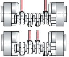
Figure 4 Double Grinding Linkage Neck

Composite machining means that all the main journals and connecting rod journals are clamped and ground. The grinding of connecting rod journals adopts advanced oscillating tracking grinding technology. The greatest advantage of this type of grinding method is its flexibility. There are two processes that can be used for compound machining: sequential grinding of the spindle journal and connecting rod journal (Figure 5) and simultaneous grinding of the spindle journal and/or connecting rod journal (Figure 6).

1
Figure 5 Grinding the main journal and the connecting rod in sequence

1
Fig. 6 Synchronous grinding of the main journal and/or pinch neck

Crankshaft deep oil hole drilling adopts gun drilling technology The deep oil hole machining of crankshaft is a difficult problem in the machining of crankshaft, especially forged steel crankshaft. The diameter of the deep oil hole in the crankshaft is generally between 5 and 8 mm, and it is obliquely penetrated from the main shaft neck to the connecting rod neck. It is a typical slender hole, and it is processed on the curved surface with poor processability. The best way to machine a deep oil hole is to use a gun drill process. Gun drill can not only be used to machine deep holes (diameter 1:250), but also can be used to process shallow holes (diameter ratio 1:1). The gun drill consists of a drill shank (for clamping tools), a drill pipe (used to connect the cutter head, determined by the length of the machined hole, using tougher materials), a drill (cutting part, tip is eccentric, hard The three parts of the alloy material are welded together with a through hole in the middle and a V-shaped groove on the outside. Relying on the middle through hole to achieve internal cooling, the cooling liquid is ejected from the small hole on the back knife and can directly cool the cutting zone. When high-pressure coolant is used, the chips can be efficiently discharged from the hole being machined through the straight V-grooves, eliminating the need to periodically retract the cutter to discharge the chips during the drilling process. When processing slender holes, the gun drill can complete the drilling, boring and reaming at a time, and the high-precision (IT6-8 grade), straightness (0.16-0.33mm/1000mm), rough can be processed with one pass. Degree (Ra3.2 to 0.1) holes. According to data from FAW-Volkswagen, when using a gun to drill the deep oil hole of the engine crankshaft, special size drill bushes must be used. The drill bushes they use are precision gun drill bushes made of hard alloy or alloy tool steel. Their hardness is HRC 63-65, and the inner hole surface roughness is Ra 1.6-3.2. The inner and outer diameters allow the maximum coaxiality error. For 2um, the maximum allowable runout error at the front face is 5um, the distance between the bottom surface of the drill sleeve and the workpiece surface does not exceed 0.5mm, the coaxiality error of the drill sleeve and the spindle does not exceed 5um, and the clearance between the drill sleeve and the gun drill bit part is maintained at 3~ Within 8um. Machine tool spindles using gun drills must have high axial and radial stiffness, and should be selected correctly for use. In general, the cutting speed Vc is 60 to 100 m/min, the feeding amount f is 0.015 to 0.03 mm/r, the hydraulic pressure P is 2.5 to 6.0 MPa, and the flow rate Q is 0.2 to 0.65 L/s. In addition, special gun drill oils are required for machining the deep oil hole of the engine crankshaft. The general gun-drilling cutting fluid should have extreme pressure additives to ensure that the oil film is formed under high pressure to prevent dry friction. The viscosity of the cutting fluid is related to the diameter of the drill hole. The smaller the diameter, the lower the viscosity. The cutting oil sent to the cutting zone of the gun drill has the characteristics of high pressure, large flow, and high filtration accuracy compared with general machining. The flow rate should increase as the depth of the hole increases to ensure that the cutting oil has a greater flow rate and achieves the goal of smooth chip evacuation. Crankshaft special processing technology Rounded corner rolling technology The crankshaft fillet rolling is the use of the pressure of the roller, forming a rolling plastic deformation belt at the crankshaft main journal and connecting rod neck transition fillet. The characteristics of this plastic deformation zone include: The generated residual compressive stress can be offset or partially canceled by the crankshaft during operation to increase the fatigue strength. Increased hardness. Rolling makes a dense layer with a high hardness at the rounded corners, thereby improving the mechanical strength and fatigue strength of the crankshaft. Surface roughness decreases. Rolled round corners can make the surface roughness of rounded corners reach Ra0.1 or less, thereby greatly reducing the stress concentration at the rounded corners and improving the fatigue strength. The roll-rolling technology applied in foreign countries is quite advanced. It can complete the rolling of all round corners at a time, and can achieve different pressures of the main journal and connecting rod journal rounding, and the same connecting rod journal rounding in different directions. The pressure on it can also be different. In this way, the best rolling effect can be achieved economically and the fatigue resistance of the crankshaft can be maximized. Tested by HEGENSCHEID, Germany, the life of the ductile iron crankshaft can be increased to 100% to 280% after rolling.

2
Figure 7 Comparison of the front and rear crankshafts

The barrel finishing and smoothing technology applied to the engine crankshaft can greatly increase the surface quality. The main working principle is: the abrasives are composed of granular abrasives, multi-functional grinding fluids and water, the abrasive tools make complex free motion in the material box, the workpiece is submerged in the abrasive tool, and the workpiece and the abrasive tool are certain. The relative speed and force of the friction, extrusion, sculpting, and micro-cutting occur to increase the surface quality. Especially for the crankshaft, finishing technology is particularly important due to the complex structure to remove burrs. The specific effects and main features of the finishing technology include: It can remove burrs more completely, sharpen the sharp edges of the sharp corners; Can remove the rust, oxide layer and defects that cannot be removed by hand, and make the surface bright and soft; Refine the surface structure , increase the value of the residual compressive stress on the journal surface; improve the assembly, improve the reliability and service life, reduce the run-in period; can greatly increase the surface profile support length Tp value, improve the surface wear resistance. Abrasive Belt Polishing The crankshaft, connecting rod journal, and thrust surface of the crankshaft require superfinishing and polishing. The traditional craftsmanship is to use the super-precision machining tool of whetstone. After machining, the geometry of the journal is severely damaged, the saddle shape (concave) is formed, and the size of the journal is greatly affected. Foreign super-finishing crankshaft crankshaft polishing process has long been used NC, and this belt is moisture-proof electrostatic sanding (guarantee sand sharp outward.) In order to polish the fillets and shaft shoulders, the belt is grooved on both sides to fit the machined surface. The foreign crankshaft belt polishing machine can polish main journal, connecting rod journal, fillet, shoulder and thrust surface at the same time. The structure adopts clip type, with 4 pads (concave type) on each journal to compress the belt; pad and belt should be selected according to the workpiece material and hardness; the winding function on the machine guarantees each axis The neck has a new belt (adjustable length) to work; the polishing method is based on the principle of super-finishing. Its efficiency and effectiveness are far superior to Whetstone. For the polishing and grinding of the ductile iron crankshaft, since the ferrite within the ductile iron forms a protruding burr after grinding, the grinding and steering of the shaft should be reversed from the working direction, and the polished steering is the same as the working steering. In this way, the burr can be effectively removed during polishing and the bearing bush can be prevented from being scratched during work.

Leather Embossing High Frequency Welding Machine

Leather Embossing High Frequency Welding Machine:

Automatic feeding table design, greatly improve the safety factor, save manpower;

NL-5557 anti-spark vacuum tube protection device;
PLC and touch screen control system;
Water cooling HF oscillation system.
High frequency stabilizer and high frequency shielding device are provided to reduce high frequency disturbance to low level.
Adopt advanced square oscillation cavity design, excellent oscillation circuit, make the stable, strong high frequency output .
Automatic overcurrent protection system can increase the service life of vacuum tube and protect mold.

Plastic Sealing Machine,Leather Embossing High Frequency Welding Machine,Shuttle Table Hf Welder Machine,Flak Jacket Welding Machine

Hangzhou Xiaoshan Wanfeng Mechanical & Electrical Equipment Factory , https://www.wfengmachinery.com